Batteries and bulbs are fun, but they can only go so far. How about a capacitor and a bulb? Yes, let’s do that.
Here is the setup.
This has a battery (2 1.5 volt batteries) connected to a 1 Farad capacitor with a switch. This capacitor is then in parallel with a light bulb. When the switch is closed, the capacitor is charged up to 3 volts. When the switch is opened, the capacitor discharges through the bulb. Notice how it slowly gets dim.
Here, I even made this same (almost the same) circuit in a PhET simulator (java warning).

Of course the full circuit doesn’t really matter. I don’t care about charging the capacitor, just the discharging. So here’s the important part.

Let’s start off by applying the Loop Rule to this circuit. If I start from the lower left corner and then go around counterclockwise, I get the following. Oh, I’m assuming zero resistance in the wires.
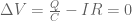
Where the voltage across the capacitor depends on the charge.

But wait! The current is the flow of charge. Since there is a current, the will be a decrease in charge on the capacitor. A decrease in charge means there will be a lower voltage. This lower voltage makes a smaller current. Maybe you can see the problem. Don’t worry, we can still solve this.
Let’s create a numerical calculation to model the current running in this circuit. The key here is to break the problem into very small time steps. Let me start by using the loop rule and using the following definition of electric current.

Now the loop rule looks like this.
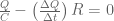
If I use a very small time step, then I can assume that during this time interval the current is constant (it’s not, but this isn’t a bad approximation). From this I can solve for the change in charge.

But what does this change in charge do during this time interval? Yup, it decreases the charge on the capacitor—which in turn decreases the capacitor voltage—which in turn decreases the current. I think I already said that.
After this short time interval, I can find the new charge on the capacitor.

Note: the minus sign is there because the current DECREASES the charge on the capacitor.
That’s it. We are all set. Here is the plan. Break this problem into small time steps. During each step, I will do the following:
- Use the current value of charge and the loop rule to calculate the change in charge during the time interval.
- Use this change in charge to update the charge on the capacitor.
- Repeat until you get bored.
OK. Suppose I am going to do this. I decide to break the problem into a time interval of 0.001 seconds. How many of these intervals would I need to calculate to determine the current in the circuit after 1 second? Yes. That would be 1000 intervals. Who wants to do that many calculations? I sure don’t.
The simplest way to do this many calculations is to train a middle school student how to do each step. It shouldn’t be hard. Oh wait, the middle school student is still busy playing Fortnite. Oh well. Maybe I will train a computer to do it instead. Yes, that’s exactly what I will do.
In this case, I’m going to use python—but you could use really any programming language (or even no computer programming language). The idea of a numerical calculation is to break a problem into small steps. The idea is NOT to use a computer. It just happens that using a computer program makes things easier.
Here is the code (below is just a picture of the code—but you can get it online too).

Let me just make a couple of comments on different lines.
- Line 4,5 just sets up the stuff to make a graph. Graphing in super easy in this version of python (Glowscript).
- Line 14 is the length of the time interval. This is something you could try changing to see what happens. Yes, if you use the trinket.io link above, you can edit the code.
- Line 21 looks tricky. It looks like Q will cancel in that equation. Ah HA! But that’s not an algebraic equation. In python, the “=” sign means “make equal” not “it is equal”. So this takes the old value of Q and then updates it to the new Q.
- Line 25—same thing happens with time. You have to update time or the loop will run FOREVER!
- Line 26. This is how you add a data point to the graph.
This is what you get when you run it.

OK. That looks nice. As we see in real life, the brightness of the light bulb dims rapidly at first and then slowly dies down. This plot seems to agree with actual data (always good for a model to agree with real life).
But what does the textbook say about a circuit like this (called an RC circuit because it has a capacitor and a resistor in it)? Note: this is an algebra-based physics textbook. It gives the following equation for a discharging capacitor.


In this case the 

Those two plots are right on top of each other. Winning. Oh, go ahead and try to change the time step. Even with a much larger step, this still works.
Some final notes. Why? Why do a numerical calculation?
- Numerical calculations are real. They are used in real life. There are plenty of problems that can only be solved numerically.
- I think that if physics students create a numerical calculation, they get a better understanding of the physics concepts.
- What if you want to treat the bulb as a real lightbulb? In that case the resistance is not constant. Instead, as the bulb heats up the resistance increases. With this numerical calculation you should be able to modify the code to account for a real bulb. It would be pretty tough if you solved this analytically.
- What is the point of having students (in an algebra-based course) memorize or even just use the exponential solution for an RC circuit. It might as well just be a magic spell if you just use the equation. I don’t really see the point. However, with the numerical calculation the students can do all the physics.

2 thoughts on “RC Circuit as an Example of the Loop Rule”